
ATLAS e-News
23 February 2011
Complete for 2009
20 October 2009
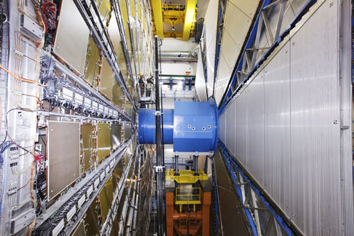
The new octagonal shielding, supported by a table of hydraulic jacks on an HF truck
At the end of August, the last major piece of the ATLAS puzzle was set in place with the installation of the octagonal pieces of the forward shielding. Much of the shielding in ATLAS remains in the cavern at all times, though it is moved around during access, but the forward shielding is completely taken out of the cavern.
The core of the forward shielding comes in three parts. The first of these is the bridge, which lies under the beam pipe, supported by a steel A-frame on one side and the permanent “nose” shielding on the other. With only ten centimetres’ clearance on either side, this is the most nerve-wracking part of the installation. The bridge supports two more pieces of shielding, which fit with it to form a cylinder. But this shielding is not quite enough to protect ATLAS from beam-related background.
Housed in the nose, the copper Target Absorber Secondaries (TAS) collimator keeps particles coming from the interaction point in ATLAS from quenching magnets along the LHC. Showers in the TAS can result in unwanted background in the muon spectrometer, so the shielding team designed an octagonal layer to back up the core in this area, sitting around the cylinder like a nut encircles a bolt.
All segments of the forward shielding are comprised of a thick layer of cast iron for hadronic showers, a thinner section of boron-doped polyethylene plastic “cladding” for slowing and catching neutrons, and finally a layer of steel plates to stop photons, some of which are produced during neutron capture.
Optimizing the shielding design has been a major challenge. “We spent more than one year filling a computer farm at Brookhaven,” says Vincent Hedberg, shielding project leader. With Monte Carlo simulations, he and Mike Shupe from the University of Arizona struggled to reduce the mass of the shielding in ATLAS without reducing its performance. And they succeeded, cutting about 1000 tonnes from the design, much of it in the forward components.
All the parts for the forward shielding were manufactured in the Czech Republic. “We benefited immensely from the support of the local Czech ATLAS teams from Charles University and the Czech Technical University in Prague during manufacturing,” says Vincent. “Not only were these groups supervising the procurement but they organised the assembly and the transport. They even participated in the assembly of the 10,000 polyethylene blocks needed for the cladding.”
The cylindrical core had been installed last year, but the octagonal shielding made for an all-new operation. “The octagonal pieces are not essential as long as we are running at low luminosity,” says Vincent. In order to support the new equipment, the technical coordination team designed a table with four hydraulic jacks, which raise and lower the bottom half of the octagonal segment. The table sits atop an orange HF truck, which can slide along the cavern floor on air pads.
On August 20th, cavern technicians in side A, under the direction of Michel Raymond, lowered the bottom half of the octagon onto the table. Then, they slid the HF truck into position under the core shielding and raised the four hydraulic jacks so that the cylindrical section lay in the hollow of the half-octagon.
The next day, they lowered the top of the octagon, resting it against the bottom half. This is the configuration during beam. “We lock the jacks in up position with large nuts,” Vincent explains, removing the risk that the hydraulics would give out and unbalance or drop the shielding. Side C was completed on August 31st.
Vincent approaches these first installations with a touch of anxiety, even though his team has tried to consider every detail in the design. “You can never be sure when you build something that you don’t make some mistake somewhere,” he says. “You’re not very sure of yourself until the last piece has come in.”
The cylindrical shielding required a different installation as well, lowering the bridge onto the HF truck and then lifting it into position with hydraulic jacks. “It was the first time that we were doing this operation, as last year we installed it thanks to the crane, before the vacuum pipe was installed,” Michel Raymond explains.
Nevertheless, the procedure went smoothly on side A, with more confidence on side C. “A lot of care had been taken in preparing the procedure and analysing what could go wrong, mainly because the clearance to install the bottom part is really small,” says Michel. “I can estimate now that we should be able to install the bottom part and top part in about 2 days.”

Katie McAlpineATLAS e-News |